I am moving my information over to www.steve.88white.com
Stop on by!
Friday, April 24, 2009
Monday, February 23, 2009
Basic Stamp - Cylon LED project
I've always been facinated by shiny blinking lights.
(Blue ones especially...)
I decided to re-create the famous 'Cylon" light pattern.
(think Knight Rider's KITT front lights going back and forth)
(Blue ones especially...)
I decided to re-create the famous 'Cylon" light pattern.
(think Knight Rider's KITT front lights going back and forth)
 Once again, I'm going to use the Basic Stamp since it's so easy.
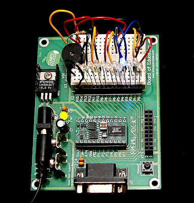
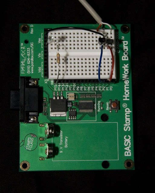
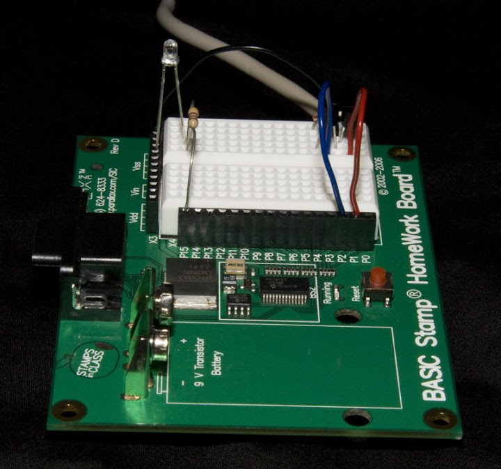
Here's the layout:
Pins 0 - 12 are connected to blue LED's
Pin 15 is connected to a pezio speaker for the cool sound effect
Line 14 is my ground bus that has a single resistor going to ground

Here's the video:
CLICK HERE for the sample BS2 code
Thursday, January 29, 2009
LCD - Basic Stamp Microcontroller
I purchased a nice 4 X 20 Character LCD off of Ebay for a much better price than most other sites. (look up www.web4robot.com for the LCD)
As you can see, it's up and running on the first night!

I noticed a few errors in the manual, so I improvised and figured out that PBASIC used $FE instead of 0xFE commands. (the 0x = $ for all the hex code)
Little bit of tweaking and I created an ASCII character

Here's the basic wiring.
On the LCD, Pin1 = power, Pin3 =RX, Pin5 = ground
I connected to Pin1 on my Basic Stamp for the TX pin

I took the time to add a lot of notes so that anyone can learn the tricks quickly.
Please excuse the video quality, but hey, it's my first attempt.
Sunday, January 11, 2009
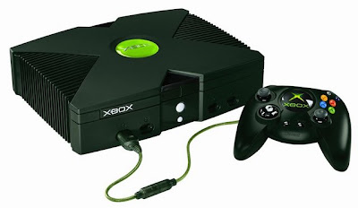
XBox Project
The 'standard' Xbox system is pretty much a computer and the controller ports are modified USB ports. Since I have an aversion to green (especially in LED's!) I decided to give this guy a makeover... GEEK STYLE
 Phase 1: Change All LED"s to BLUE

Phase Two: Fix the 'jewel' to be frosted clear and.... BLUE

Night shot

Night shot with error message

Phase Three: Add the skin

 There's no way I was going to allow the XBox controller to be green.

 Phase 1: Change All LED"s to BLUE
Phase Two: Fix the 'jewel' to be frosted clear and.... BLUE

Night shot

Night shot with error message

Phase Three: Add the skin
 There's no way I was going to allow the XBox controller to be green.
Here's my version with BLUE plastic and LED's.
Oh yeah... and the LED's light up with the rumblers!

Even the 'jewel' lights up when you power on the system.Box Computer Project
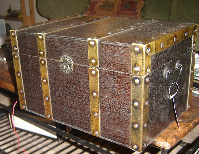
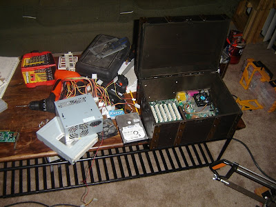
Ever wanted a computer that looks more like a decorative piece rather than an ugly box? Me too.... I was looking for a computer to put in my entertainment center that would not stand out too much.
The motherboard fit very snug and it was fun squeezing everything into the small box.
I built supports for the board and disassembled everything I could to save space.
What better way to turn the computer on and off but with a wireless remote?
I hacked apart a wireless doorbell and used the computer's power supply to power it.
In the end, the box looks nearly identical to the original box. I added an in/out fan system to create more airflow through the box later even though I had no heat issues. There is also a touch sensitive switch on the side of the box that is flush mounted just in case you wanted to turn the PC on directly. Lastly, I used fiber optic cable to port the LED indicators out to the side of the case. (very subtle). When it's all up and running, you can barely tell. The video cable goes straight out of the back of the entertainment center and into the T.V. I used a wireless keyboard and mouse that can get stashed under the coffee table for surfing the web.
Here is the box I decided to work with. $20 from TJMaxx
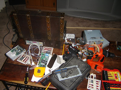
My work area at the time was my coffee table, and yes, I did use my couch to muffle the sound of the jigsaw when the time came.

The motherboard fit very snug and it was fun squeezing everything into the small box.
I built supports for the board and disassembled everything I could to save space.

What better way to turn the computer on and off but with a wireless remote?
I hacked apart a wireless doorbell and used the computer's power supply to power it.

In the end, the box looks nearly identical to the original box. I added an in/out fan system to create more airflow through the box later even though I had no heat issues. There is also a touch sensitive switch on the side of the box that is flush mounted just in case you wanted to turn the PC on directly. Lastly, I used fiber optic cable to port the LED indicators out to the side of the case. (very subtle). When it's all up and running, you can barely tell. The video cable goes straight out of the back of the entertainment center and into the T.V. I used a wireless keyboard and mouse that can get stashed under the coffee table for surfing the web.
Saturday, January 10, 2009
Microcontroller - Putting It All Together
(reserving spot for final setup)
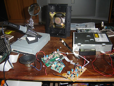
Now it's time to put all the parts together.
I have the computer interface, software, firmware, and the hardware.
List of materials:
(1) Computer
(1) Camera
(1) Basic Stamp Microcontroller
(1) Photogate Trigger (when an object breaks a light beam the camera takes a picture)
(1) Bowl of water
(1) Funnel full of water (water flow controlled by a servo)
As you can see from this picture, it's an elaborate setup just to capture a drop of water the moment it hits the bowl of water. Meh.... it's what I do :)

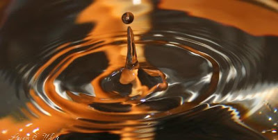
Final Result:
Here are some of the pictures that were taken thanks to the help from the microcontroller.
(pic 2)
(pic 3)
Microcontroller - The Electronics
Now for the really fun part.... the Electronics!
I started off going through the projects in the book to get a good idea of how it all works together. As usual, I never could resist making everything unique.... within the first hour I was creating my own electronic circuits and wound up losing another night of sleep.
Here is a quick example on how I tested the Visual Basic code and the Basic Stamp code at the same time.
(enter picture here..... )
Yes, simple LED's configured so that when the corresponding 'Pin' is '1' then it would light up.
Nothing fancy but it sure helped work the bugs out of the serial communication code.
Note: The microprocessor can control a certain number of 'Pins' by executing a '1' for ON and a '0' for OFF. By controlling which pins are off and on, a programmer can control just about anything.
Individual Items:
Camera Trigger - I found THIS SITE that gave a quick and easy answer on how to use the microcontroller to take pictures. I (of course) modified it somewhat.
Here are three shots showing the circuit in action
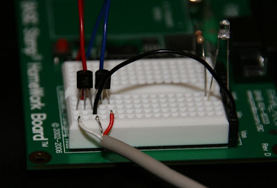
*Note: The LED is just for testing and is not needed
Sensors - I found HiViz after some searching around and they offered a simple answer to creating circuits that will help take pictures of fast moving objects . I'm going to purchase one of each kit and mash them together and control them with the microcontroller. (go figure)
Microcontroller - I'm going to stick with the Basic Stamp 2 this time around.
Subscribe to:
Posts (Atom)